Last Revised: 26MY2002
CHEVROLET A-CAR FAST RATIO POWER STEERING GEAR UPGRADE
INTRODUCTION
This paper is written to assist Chevrolet A-car owners in locating parts and components that can be used to install a fast ratio steering gear in their vehicle.
Most
Chevelle A-car vehicles that were built in the 1964 through 1974 time frame
came from the factory with Saginaw Steering Gear Division model 700 power
steering gears. Most had gear ratios in
the 15:1 range. A listing of 1964
through 1974 Chevelle power steering gears with ratios, efforts, t-bar size,
and travel is available from the websight where you obtained this paper or from
the author.
With
modern radial tires and performance suspension enhancements, many enthusiasts
would like to improve their steering gear ratio to a rapid 12.7:1. The steering ratio of a steering gear is the
number of degrees that you rotate the steering wheel (and therefore the gear
input shaft) in order for the output shaft to rotate one degree. The lower the ratio number, the faster the
steering. This paper is written to
assist Chevrolet Chevelle, El Camino, and Monte Carlo enthusiasts in swapping
their slower ratio power steering gears for a fast ratio 12.7:1 model 700 power
steering gear. Please note, there is a
new Saginaw model 600 power steering gear that is also available with a 12.7:1
ratio. However, this gear is not interchangeable with the model 700
gear.
Recommended replacement model 700, 12.7:1 ratio, Saginaw recirculating ball gears are listed on the following Excel spread sheets:
1985 – 1996 Caprice, Monte Carlo, & Buick Fast Ratio Gears
1992-98 Jeep Grand Cherokee Fast Ratio Gears
I do not recommend Camaro fast ratio gears because they have restricted travel and generally have high steering efforts. They can be disassembled and the travel restrictors removed but that is best left to someone very familiar with rebuilding Saginaw recirculating ball steering gears.
THE SAGINAW RECIRCULATING BALL POWER STEERING GEAR
The Delphi Saginaw Steering Systems (formerly Saginaw Steering Gear Division, GMC) recirculating ball, model 700, integral power steering gear is a marvel of longevity. The basic concept and most major components that make up the gear assembly started production in the early 1960s and are still being manufactured today.
There are a couple of interface areas that have remained the same from 1964 to the present. Let’s look at the attachment areas that you will not have to worry about if you decide to make a fast ratio gear installation. The three tapped gear mounting holes are in the same location and are the same thread (7/16-14 UNC) all the way from the middle 1960’s right through today! The pitman shaft serrations and the pitman arm lock nut are still the same. So this gear will bolt up right to your frame and your power steering pitman arm and steering linkage will bolt right on as well.
Some of the changes that did occur throughout the years of production are as follows:
1). The input shaft was reduced in diameter from 13/16 inch OD to ¾ inch OD in 1977. 2). Starting with the 1980 model year, the inlet and outlet ports on the gear were converted from conventional 45 degree flare fittings with 5/8-18 UNF and 11/16-18 UNF female ports to o-ring connections with 16x1.5mm and 18x1.5mm female ports.
All of the fast ratio steering gears that we are looking to swap into our A-cars were produced between 1982 and 1998. Therefore, in order to install a fast ratio gear in your car, you will need to accommodate the above listed changes.
Let’s review the interface parts one by one:
GEAR INPUT SHAFT TO FLEXIBLE COUPLING
The
original steering gear in the 1964-1974 A-car had a 13/16 inch OD input shaft
with splines and a flat. The new fast
ratio gear has a ¾ inch OD input shaft.
We will need a new flexible coupling to connect to the gear. The following vehicles were produced with
flexible couplings that will attach to the new gear:
1977
thru 1982 Chevrolet and GMC C/K (2 wheel and 4 wheel drive) Pickup Trucks
1977
and 1978 Camaro, Firebird, and Nova
1979
Nova
1983
thru 1986 Chevrolet and GMC C (2 wheel drive only) Pickup Trucks
I
have found a flexible coupling in the GM parts system that will connect to a ¾
input shaft. It is available through GM
dealers. It is part number 7826542. It is fairly expensive (around $80 list) but
it is brand new.
Be
sure to get the attaching pinch bolt, nuts, and lock washers when you purchase
the flexible coupling. Flexible
couplings attach to the steering gear with a special pinch bolt
(#7807271). This bolt can be purchased
from any GM dealer. Make sure that you
use this correct bolt to fasten the flexible coupling to the gear. Please note, if the column flange is also
detachable, you may require still another one of these special pinch bolts.
STEERING COLUMN TO FLEXIBLE COUPLING
Another
thing that we have to take into account is that the A-car steering column and
the connection to the flexible coupling went through a couple of design changes
between 1964 and 1974. These
differences will also need to be addressed.
1964, 65, 66 STEERING
COLUMNS
The
1964 - 66 Chevelle steering columns had a long steering shaft that extended
from the end of the steering column down toward the steering gear. Some of them had a detachable column flange,
others had a stamped flange that was staked in place. The flexible coupling on the gear bolted to it. This early flexible coupling was different
from new couplings in that it had two different diameter stop pins and the two special
5/16-24 UNF attaching bolts. The newer
flexible couplings have different sized attaching bolts (one 5/16-24 UNF and
the other a 3/8-24 UNF) along with equal sized stop pins.
In
order to attach the new flexible coupling to the old flange you have two areas
that require modifications. One involves
the mounting bolts; the other requires additional clearance to one of the stop
pins.
The
original A-car flexible coupling had two special 5/16-24 UNF attaching
bolts. Our new flexible coupling has one
large 3/8-24 UNF coupling bolt and one that is the same design (5/16-24) as the
bolts in our original coupling. My choice
is to drill out one hole on the column flange so that it can accept the special
3/8-24 bolt on the new coupling.
THE
FOLLOWING APPLIES TO A DETACHABLE FLANGE:
Place
the column flange on a table so that the face that mounts to the flexible
coupling is down. Place the pinch bolt slot
at the 12 o’clock position. You want to
drill out the hole that is at the 9 o’clock position to 0.381 diameter. Do not enlarge the hole too much. The 3/8-24 bolt on the new flexible coupling
has a fairly narrow shoulder that must seat against the column flange. Just enlarge the hole until the threads on
the 3/8-24 bolt just pass through. This
is the modification I prefer because now the column flange will only assemble
to the flexible coupling one way. You
don’t run the risk of having your steering column attached upside down.
The
other choice is to remove the larger bolt (the 3/8-24) from the new coupling
and replace it with a one of the special 5/16-24 bolts that you can remove from
your original flex coupling. Use the
original four tanged retainer to keep the bolt in place. Since the column flange can now be assembled
either way, you now have to remember that the 35 year old 5/16-24 bolt goes
into the hole located at the 9 o’clock position on the column flange.
The
last modification that you will have to make is to open up one stop pin clearance
notch on the column flange. With the
column flange in the same position describe above; take a look at the stop pin
clearance notch located at the 6 o’clock position. You will need to take a file or a high speed grinding tool and
increase the size of the notch by 0.070 inch around its entire shape. (See
Figure #1). This will gain you
clearance around the large rivet on the new coupling.
THE
FOLLOWING APPLIES TO A STAKED, STAMPED FLANGE:
You
basically are going to modify this stamped flange similar to the instructions
above for the detachable flange.
However, you will be working from the coupling side of the flange
(opposite from the detachable instructions).
You will probably have to remove the column in order to gain access to
the stamped flange. You will first have
to open up the smaller of the two stop pin notches by the same 0.070 inch (same
as above). Now, after opening up the
stop pin notch and looking at the flange from the coupling side, open up the
bolt hose counterclockwise from the notch to 0.381 diameter.
1967 THROUGH 1974 STEERING
COLUMNS
These
Chevelle steering columns either had long, collapsible, steering shafts that
extended down to the gear from the end of the steering column or they had separate,
intermediate steering shafts that bolted to the column up by the dash. In either case, both type shafts have column
flanges that attach to the flexible coupling.
These column flanges should have two different sized bolt holes and clearance
notches for two large rivets. Therefore
they should be compatible with your new flexible coupling without any
modifications. (See Figure #2)
POWER STEERING PUMP –
PRESSURES AND FLOWS
Where
the Saginaw model 700 gear is known for its longevity, the Saginaw power
steering P-pump has been around an equally long time. You most likely want to use your original pump with its reservoir
and pulley. The good news is that your power
steering pump can be quite easily upgraded for pressure and flow to work with
your new fast ratio gear. The fitting
on the back of the pump regulates the amount of oil flow from the pump. The flow control plunger, (which is inside
the pump directly behind the fitting) controls the pressure relief. These parts are very interchangeable between
various Saginaw P-pumps.
The
Chevelle power steering pumps (before 1970) had relatively low pressure relief
settings (950 psi). With modern wide
tires and a fast steering ratio steering gear, you will probably want to
increase the pressure relief setting of your pump. 1970 and later pumps had pressure relief settings of 1400 psi, so
they should be very adequate.
Also,
from 1964 through 1969 the Chevrolet power steering pump outlet incorporated a
male fitting and therefore required a pressure hose with a female nut to
connect to it. Starting in 1970 the
fitting was converted to a 5/8-18 UNF female port with a 45 degree flare seat (the
same as the rest of GM). Since your new
fast ratio gear has metric ports you might even consider getting rid of either
of the previous fittings that you have in your original pump and converting to
a 16x1.5mm metric discharge fitting as well.
If
you can obtain the pump that originally came with your fast ratio steering
gear, this is the safest and best approach toward obtaining the discharge
fitting and the flow control plunger that will give adequate flows and
pressures for your steering system.
Another approach is find a P-pump used in Chevrolet and GMC C/K trucks that were built after 1979. Also the new lines of GM light duty pickups and SUV vehicles have P-pumps that can be used. These are the trucks with Chevrolet 4.3L V6, small block, or big block V8s. These pumps will all have 16x1.5mm metric discharge fittings.
However, if you have an early P-pump (1964 through 1969) and still want a 5/8-18 UNF female fitting with a 1400 psi pressure relief , you will need to find a P-pump from a 1976 through 1979 four wheel drive K-truck (not the two wheel drive C-truck).
Once
you have the pump that you want, you will need to remove the discharge fitting
that screws into the back of the pump. Then,
you need to probe inside the discharge cavity and using a magnet or just
tipping the pump you should be able to remove the flow control plunger (See
Figure #3). This is the device that
sets the pressure relief and it will interchange right into your original pump. Make sure that you install it correctly. First assemble the spring then the flow control
plunger. Note, make sure that you
orient the plunger so that the screen side of the plunger goes into the pump
first.
POWER STEERING HOSES
I
don’t have any expertise with aftermarket power steering hoses. So I am not familiar with what types of end
configurations, bends, etc that are available.
If you are able to get the set of hoses from the vehicle that supplied your
fast ratio gear, you might get lucky.
They just might fit your car!!!
So this is one area that I am going to have to leave you to your own
means.
The
most straightforward approach would be to use power steering hoses with metric
fittings that screw directly into the ports of your fast ratio gear. Modify your pump as described earlier to also
use a metric female discharge fitting.
However,
if you want to remain with 45 degree flare fittings, there are adapters that
can convert the female metric gear ports (18x1.5mm high pressure port –
16x1.5mm low pressure return line port) to 45 degree flare ports. As described in the pump section, you can
quite easily modify your pump for either a female 16x1.5mm o-ring port or to a
female 5/8-18 UNF 45 degree flare port by finding the appropriate pickup truck
P-pump.
SOME PARTING WORDS
I
strongly recommend refilling your power steering system with genuine GM power
steering fluid. There are fluids that
are labeled power steering fluid, but the only one used by General Motors as
original factory fill is the one I recommend.
The amber colored fluid, available from any GM dealer was specifically
formulated to work in the Saginaw power steering pump. For maximum durability use GM steering fluid
(GM #1050017 32oz).
I
have (to the best of my ability) gathered the following information from
engineering drawings and by speaking to people that worked on the power steering
systems used in your Chevrolet A-car.
Please be aware, a lot of this information is well over 30 years
old. Also, you should always follow
procedures, instructions, and torque recommendations provided in shop manuals
and other reliable sources when assembling and disassembling the components in
your power steering system.
A FINAL PARTING WORD
Please don’t go running for a lawyer to sue my butt if you purchase a cheap donor part and something doesn’t work exactly as I described. In fact, if you have a problem, do other Chevelle and Elky owners a favor and be sure to get back with me so I can update this information and keep it as accurate as possible.
Figure #3
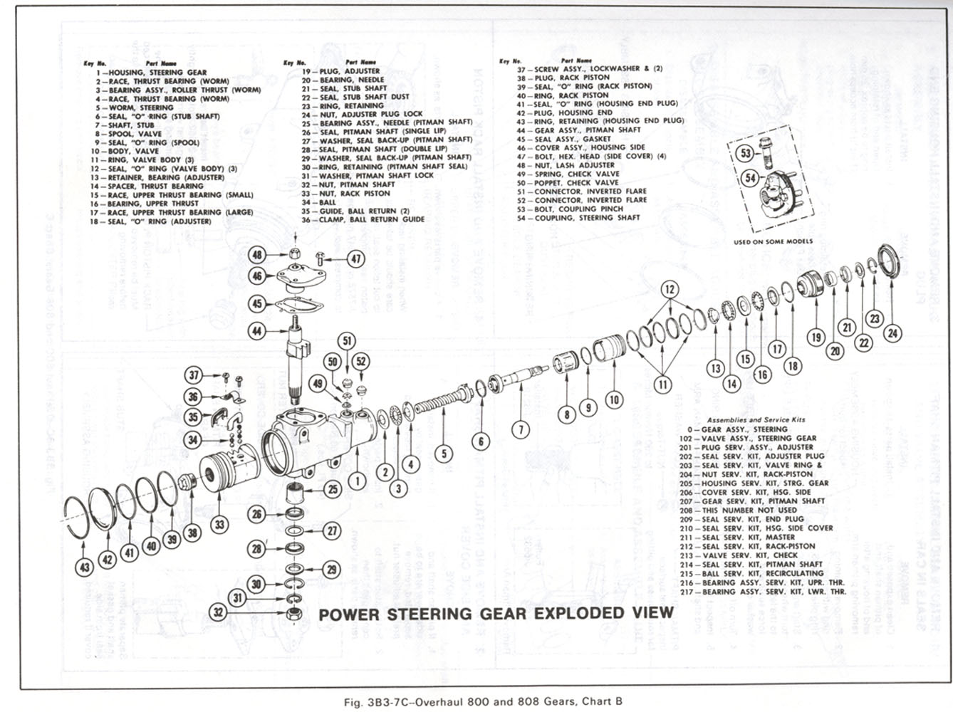 Exploded View of a 800 Gear Box
Detail dismantling of a Saginaw 800 Gear Box -OR- Send to Printer Version
A-CarFastRatioGear.doc
JIML82@aol.com